






Subsea Weld NDT Comparison: 6 Inspection Methods Explained
A subsea weld NDT comparison of UT, PAUT, ACFM, MT and RT, covering detection limits, underwater deployment challenges and how to pick the right method.
A subsea weld sits behind depth, current, and marine growth, largely out of sight and out of reach. Non-destructive testing (NDT) is how operators check its condition without cutting into the structure, catching cracks, porosity, and corrosion before they compromise a riser, pipeline, or platform.
Underwater, method choice depends on access, visibility, surface condition, and how reliably a sensor can be held in place, not just the expected defect type. This guide compares the six NDT methods used on subsea welds and how to select the right one for a given inspection.
What is subsea weld NDT?
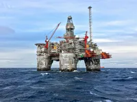
Subsea weld NDT is the inspection of underwater weld conditions without cutting into or damaging the structure. It covers welds on risers, pipelines, jackets, and subsea manifolds on offshore platforms and FPSOs. The purpose is to identify cracks, porosity, and corrosion while defects are still small enough to schedule a repair, rather than after they have compromised structural integrity.
Why subsea weld inspection is challenging
Underwater access and visibility
Many subsea welds sit in tight spaces between structural members, out of easy reach for a fixed camera angle or a hand-held probe. Visibility is often limited by turbidity or depth, so inspection increasingly relies on instrument data rather than a direct view of the weld.
Surface condition and marine growth
Marine growth, corrosion products, and coatings build up on subsea structures over time and often need clearing before inspection can begin. Some NDT methods tolerate light buildup better than others, which affects how much surface preparation a job requires.
Equipment deployment
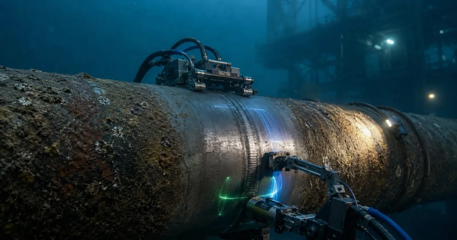
Current, depth, and confined geometry make it difficult to hold a sensor steady and repeat a scan position exactly. Remote deployment platforms address this by providing a stable, repeatable way to position inspection equipment against a weld, without depending on a diver holding a fixed position in moving water.
NDT methods used for subsea weld inspection
Visual testing (VT)
Visual testing is typically the first step in a subsea inspection. Cameras, and in some cases divers, examine the weld for visible surface issues such as gross corrosion, deformation, or coating damage. It is fast and low-cost, but limited to defects large enough to see directly.
Ultrasonic testing (UT)
Ultrasonic testing sends sound waves into the weld through a probe and reads the echoes reflected by the material or by internal flaws. It is a standard method for measuring wall thickness and detecting internal defects such as porosity or lack of fusion, and it is widely used across subsea inspection programmes.
Phased array ultrasonic testing (PAUT)
PAUT extends conventional UT by using multiple small elements to steer and focus the sound beam electronically, producing cross-section images and defect maps rather than a single reading. It requires more equipment and training than conventional UT, but gives a more detailed, repeatable picture of complex weld geometry, which is useful on critical structural connections such as risers.
Magnetic particle testing (MT/MPI)
Magnetic particle testing magnetises the weld and applies fine ferrous particles that gather at surface cracks, making them visible. It is well established on steel welds. Underwater, results depend more on visibility and on the inspector’s interpretation of the particle pattern than electronic methods do.
Radiographic testing (RT)
Radiographic testing uses X-rays or gamma rays to image the internal structure of a weld. Water absorbs and scatters radiation, which increases exposure time and requires precise positioning of the source and detector. This makes RT harder to deploy underwater, and it tends to be used selectively rather than as a routine subsea method.
ACFM and other advanced methods
Alternating current field measurement (ACFM) passes an electrical current across the weld surface and measures how the resulting field distorts around a crack. It works through coatings, rust, and light marine growth, reducing the surface preparation needed, and returns a computed crack size rather than a visual estimate. This is part of why ACFM has become a common choice for subsea crack sizing on coated or lightly fouled welds.
Comparing subsea weld NDT methods
Surface and near-surface defects, common in welds under cyclic stress, are best identified by ACFM and magnetic particle testing. ACFM detects small surface cracks and returns an automated size estimate, while visual testing only catches defects large enough to see directly.
Internal defects such as porosity or incomplete fusion call for UT or PAUT. PAUT adds the ability to locate and size a flaw within the weld cross-section, supporting fitness-for-service decisions. RT can also detect internal defects, but underwater deployment constraints limit how often it is used.
Data output differs by method. ACFM and PAUT produce digital records that support comparison against earlier surveys. MT and VT depend more on the inspector’s real-time interpretation.
Which NDT method is best for subsea welds?
No single method covers every case, since the right choice depends on the defect type and the weld’s risk profile. For surface cracks, ACFM is often preferred on coated or lightly corroded welds, with magnetic particle testing a suitable alternative on clean, accessible surfaces. For internal defects, PAUT suits complex geometry, while conventional UT remains a standard, lower-cost choice for thickness checks and early wall-loss detection. For high-risk or structurally critical welds, such as riser connections, combining more than one method is common practice.
When should multiple NDT methods be used together?
ACFM and PAUT are frequently paired because they target different defect types and can cover areas where one method alone has limited access, such as a weld partially shadowed by an adjacent structure. Running both increases confidence that a defect has not been missed, and this combination is typically reserved for the highest-risk welds in an asset integrity programme.
How to select the right subsea weld NDT method
Start with the weld and asset requirements: weld type, material, geometry, and the governing inspection standard. Then identify the expected defect type, since welds under cyclic loading usually call for surface crack detection first, while welds in corrosive service need closer attention to internal wall loss. Account for the inspection environment, as depth, current, access, and surface condition determine which methods are practical to deploy. Finally, confirm reporting and personnel qualification requirements, since subsea NDT work is typically governed by class society and operator standards.
How ROVs are changing subsea weld inspection
Reducing reliance on manual positioning
Positioning inspection equipment by hand underwater is difficult to do consistently, particularly in current or at depth. An ROV, an underwater vehicle piloted remotely from the surface, provides a stable platform that holds a sensor in place during a scan and can repeat that positioning across multiple inspection cycles, reaching tight spaces between structural members that are hard to access manually.
Combining inspection methods on one platform
A single ROV can carry a camera for visual inspection alongside instrumented sensors, such as an ultrasonic thickness probe, as a payload. This allows one deployment to cover both a visual check and a data-backed reading.
Understanding ROV technology for subsea inspection
An ROV provides the underwater platform for cameras, sonar, and inspection sensors, controlled from the surface through a tether. It does not perform NDT on its own. It carries the sensor or probe to the weld and holds it in position while the sensor collects data. See what is an ROV for a fuller overview, and ROV inspection for how inspection programmes are structured across asset types.
Choosing an ROV for subsea inspection applications
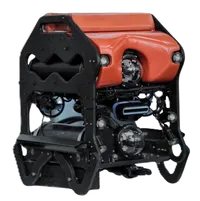
The right ROV for a subsea weld inspection depends on depth rating, payload capacity, and the stability needed to hold a sensor steady during a scan. EyeROV SAGARA is built for open-water inspection work of this kind and can carry a UT probe as a payload for subsea weld thickness measurement. Data collected during an inspection can be processed and reported through EVAP, EyeROV’s post-processing and analytics platform.
Make every subsea weld inspection count
Subsea weld integrity affects the safety, reliability, and service life of critical offshore assets. Selecting the right NDT method, and deploying it on a stable underwater platform, supports more consistent inspection outcomes across a programme. Contact EyeROV to discuss ROV-based inspection support for oil and gas assets.
Frequently Asked Questions
Can ultrasonic testing be performed underwater?
Yes. Ultrasonic testing is a standard underwater inspection method, using equipment built for wet deployment and probes held in position by a diver or an ROV-mounted scanner. See ROV inspection for how this is typically deployed.
What is the difference between UT and PAUT for weld inspection?
Conventional UT uses a single fixed-angle probe and is suited to thickness checks and basic flaw detection. PAUT uses multiple elements to steer the beam electronically, producing faster scans and more detailed imaging for complex weld geometry, at a higher equipment and training cost.
How do you choose the right NDT method for an offshore weld?
Start with the expected defect type, surface or internal, along with weld geometry, surface condition, and the applicable inspection standard. High-risk or complex welds often call for pairing a surface method such as ACFM with a volumetric method such as PAUT.